Interface
このコンテンツはまだ日本語訳がありません。
Interface
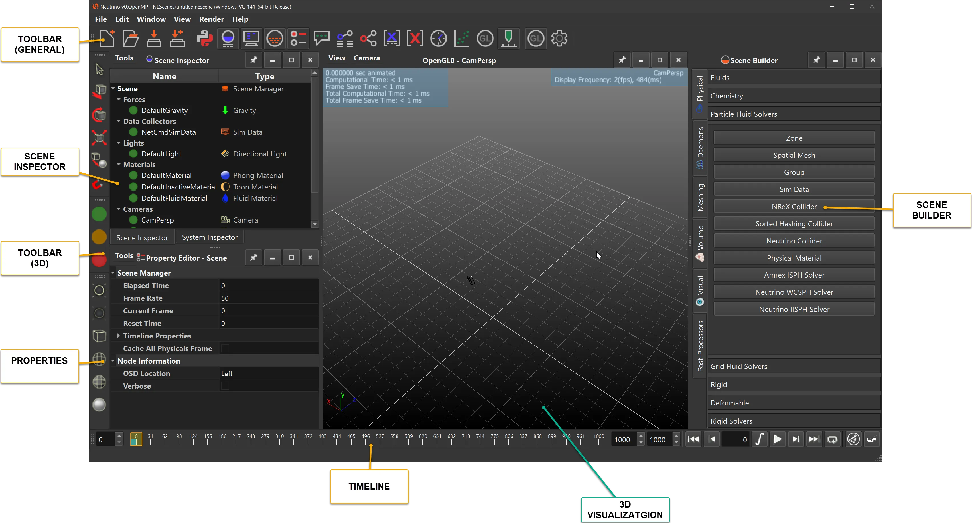
Neutrino’s user friendly interface enables easy setup of models for simulation. Parameters and operators can be added easily to perform the various operations. Interface items are depicted below.
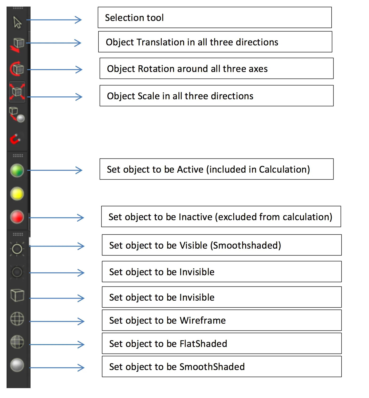
Toolbars
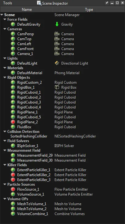
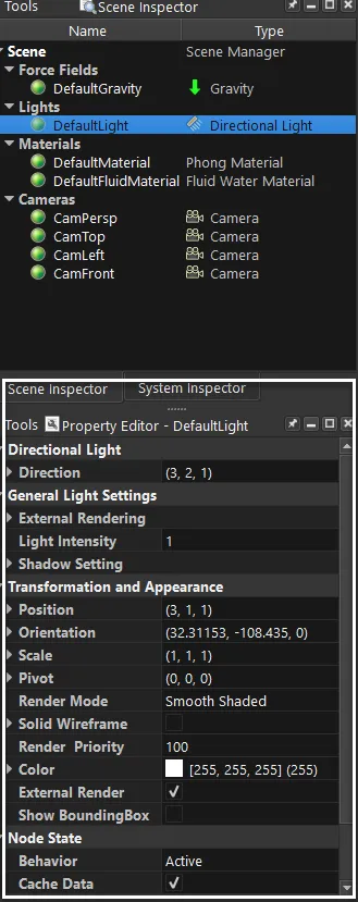
Scene Inspector
Property Editor
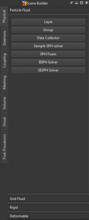
Scene Builder
System Inspector
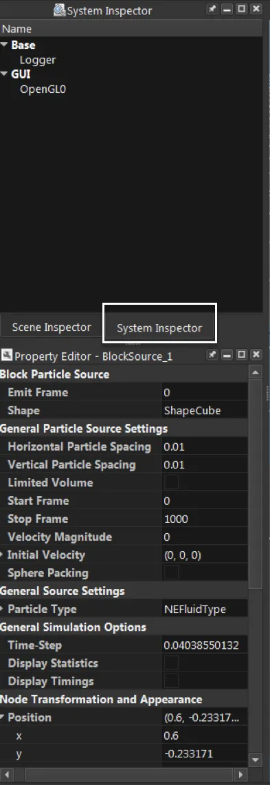
Base
| Parameter | Description |
|---|---|
| OpenMP Threads | Number of Threads Neutrino will use for Simulation (8) |
| Server Port | If Neutrino is controlled by external communication protocol the socket number (20200) |
| Scene Path | Specify the information needed to be exported. |
| Data Read Directory | Specifies the directory where all the caches for entries in the scene reside |
| Data Write Directory | Specifies where the cache data will be written onto |
| Optimize Net Caches | In certain cases setting this will optimize block writes onto network drives |
| Compress Fluid Caches | This will create fluid caches with compression but for large particle counts this might result in performance loss |
GUI
| Parameter | Description |
|---|---|
| Timeline Units | Number of Threads Neutrino will use for Simulation (8) |
| Save OpenGL Frames | If Neutrino is controlled by external communication protocol the socket number (20200) |
GL Properties
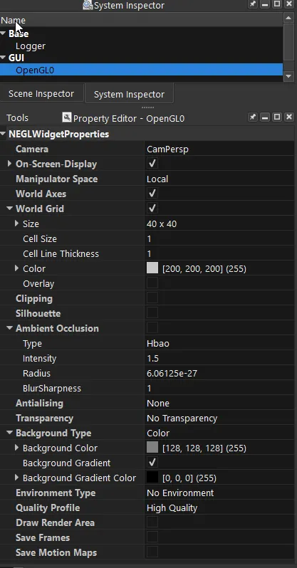
A Neutrino session can have several interactive views for visualization and model setup and the main engine to render them is OpenGL. Its properties are as follows:
OpenGL
There can be many OpenGL objects depending on how many views are present in the scene. By default this is 1. The views can be split according to user specification and the View menu described later controls the splits and usage of multiple visualization/model setup views.
The main properties control the render of each of these views.
| Parameter | Description |
|---|---|
| Camera | The Camera used for rendering this view |
| On Screen Display | Whether or not to display statistics |
| Manipulator Space | Local Space operates with respect to the center of the object. |
| World Axes | The axes ON/OFF in the visualization window |
| World Grid | Whether a flat grid is drawn in the visualization or not |
| Clipping | Uses a normal for clipping objects - Deprecated in favor of a Clipping Object |
| Silhouette | Unused and deprecated |
| Ambient Occlusion | Turning this on produces self shadows and better looking renders (HBAO) |
| Antialiasing | The method used for improving quality of lines etc in the gl/visualization window |
| Transparency | The transparency method used - different modes are a trade-off between quality/time |
| Environment Type | The background image used in visualization (either cube 6 sides or sphere |
| Quality Profile | The render quality used for preview/visualization. Some features are turned off/on for |
| Draw Render Area | Not used |
| Save Frames | Save the frames displayed in this specific visualization window/GL to file (png) |
| Save Motion Maps | DEPRECATED |
Timeline

The two modes are Simulate and Playback. Simulate mode is activated by the button. The play button is then used to either simulate (Simulate Mode) or Play (Playback Mode).


Turns Green when armed and ready to simulate
Simulation is Armed to proceed. Next Play would actually Simulate the scene.

Run simulation if Armed or just playback the recorded simulation from caches if not armed.
Connection Inspector
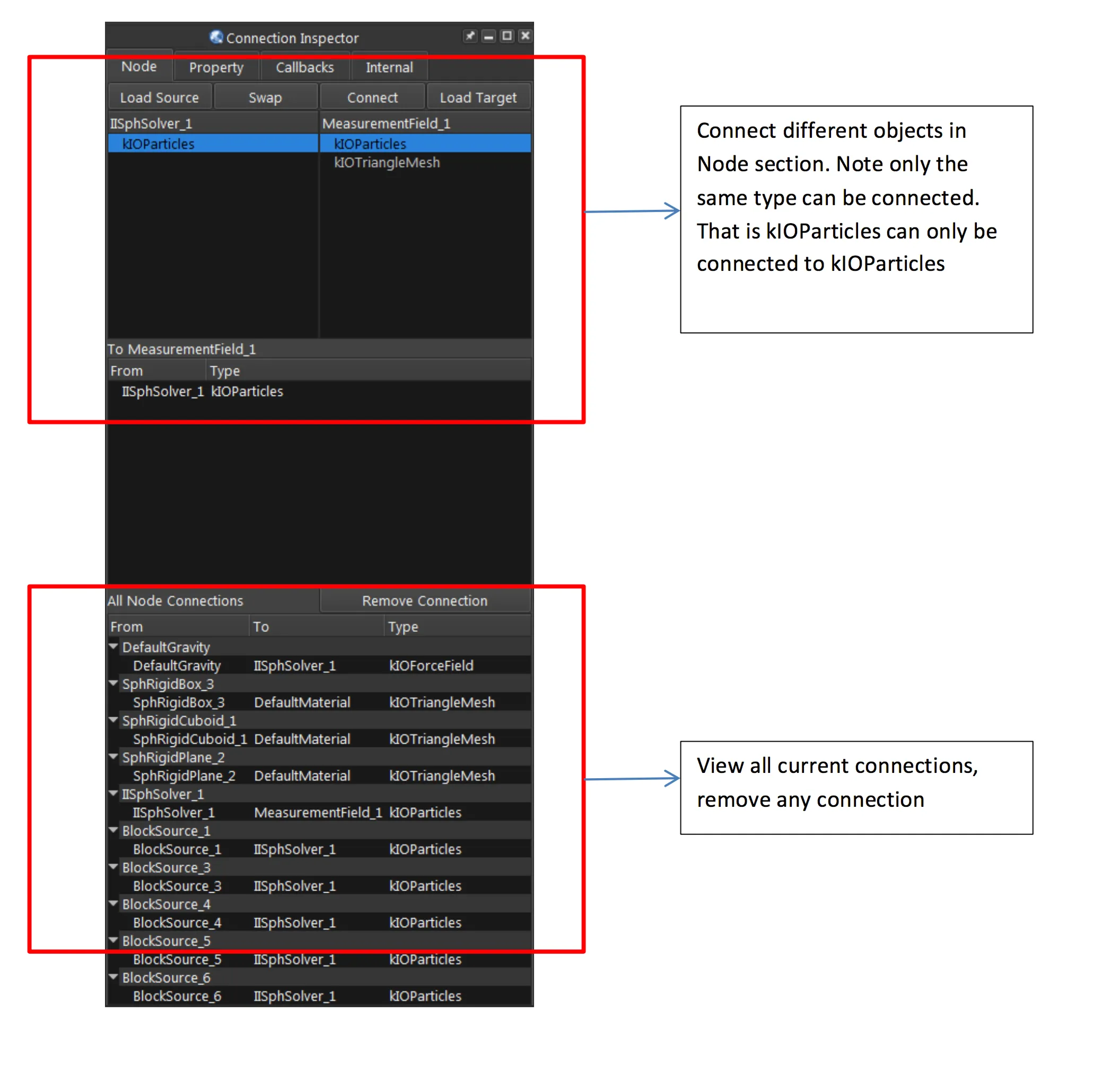
Connection Inspector is used to connect various inputs and outputs from nodes to process during simulate/playback mode. The emitter’s creates Particles (kIOParticles) which is connected to the solver’s input. Solver’s output (kIOParticles) can be connected to the Measurement Field’s input (kIOParticles).
In Neutrino you can consider all the objects displayed in the Scene Inspector to have inputs and outputs and they are evaluated during a simulation. For example the output of a particle emitter would be particles (kIOParticles) and that is automatically connected to the input of a solver (kIOParticles). Some connections are automatically made for example in this case. But for some other cases the user has to make the connections manually depending on what the scenario is. If the particle emitter’s kIOParticles to the solver connection is deleted then there would be no particles input to the solver and hence no solve. Neutrino node’s most common inputs/outputs are the following: kIOParticles, kIOTriangleMesh, kIOVolumes
Script Editor
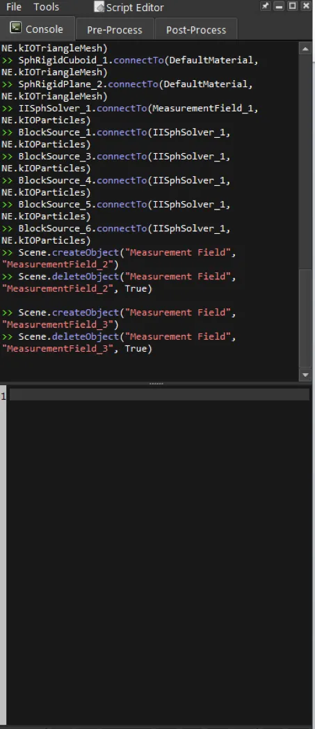
Script Editor Commands
Script Editor could be used for performing any action in Neutrino but through the python interface. The python interface to Neutrino’s system is explained in a separate section.
Node Graph Editor
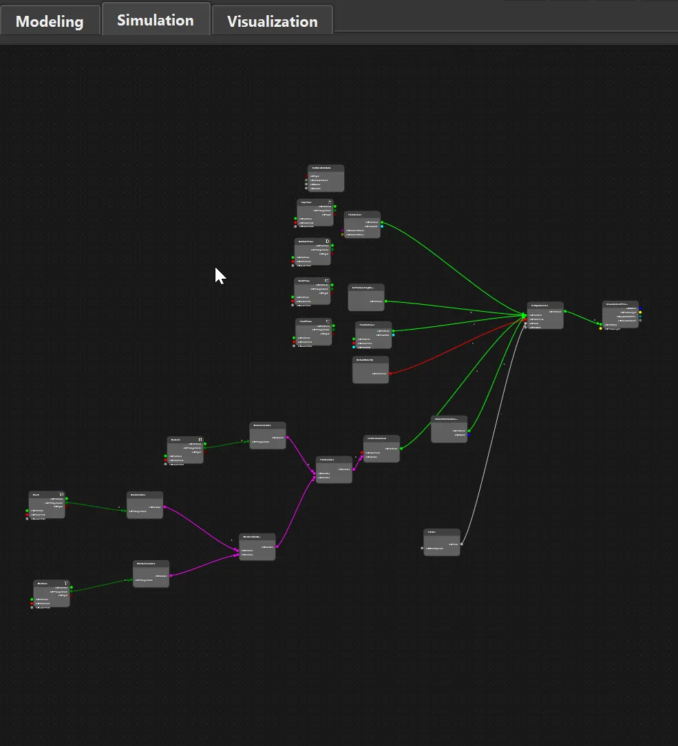
Node Graph Editor, used to visualize various connections. It can be seen clearly that all fluid objects go to NIISPHSolver and measurement field takes data from IISPHSolver to determine the parameter we are interested in.
Currently its still under works and mainly used for volume connections.
Interactive View Window
Objects can be selected, transformed in the world space visible through the selected camera in the GL Widget View. There can be many such views which can be created and deleted in the scene and they are synchronized with each other.
Each view can be split into 2 duplicated and assigned different cameras on the View Menu on top of this window
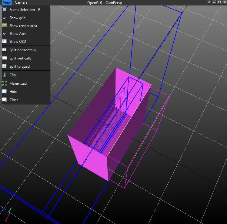
If you select an object and select the translate (toolbar) on the left side a translate handle appears in the gl preview window. you can select each of the arrows in the axes and move them around and that moves the object. Same goes for scale and rotate, their tools are in the left toolbar.
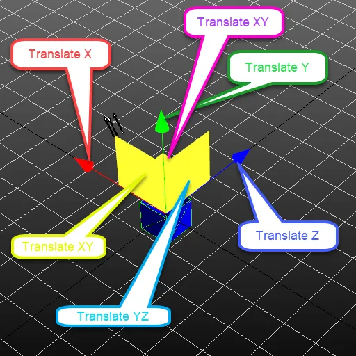
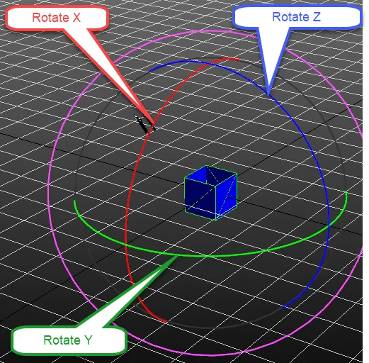
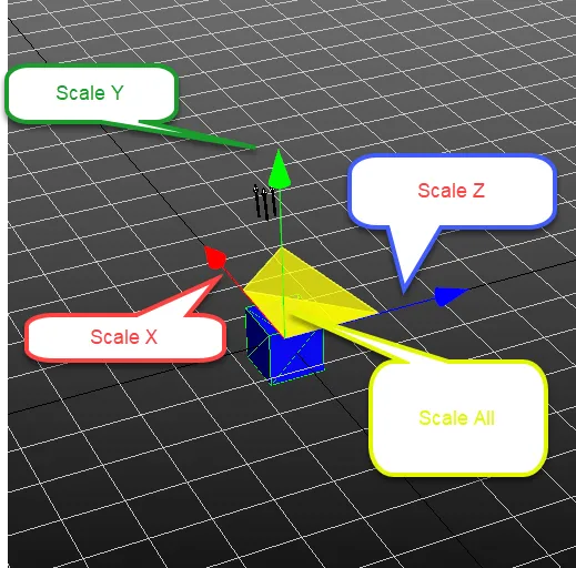
The camera for the view is selected from the Camera Menu item at the top of the View Window
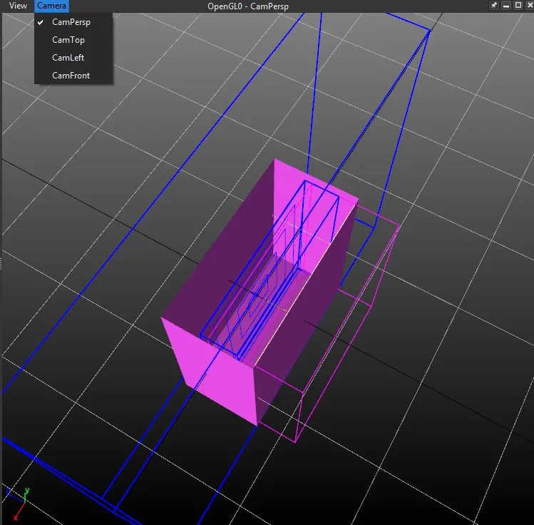
Camera
Alt and mouse will turn the camera around
Alt + middle will pan the camera
Alt + Right will zoom in/out
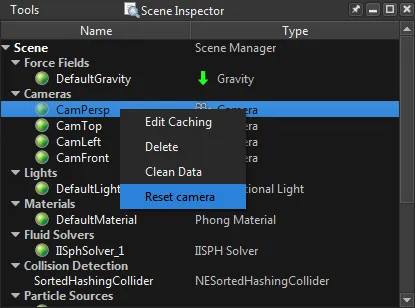
If a camera gets stuck somewhere you can reset it by selecting the camera in the scene builder and third mouse button and reset camera.